Started working on the turbo flange. I'm keeping the hot side divided between banks, so I used 2 2" schedule 40 elbows to connect to the flange. Here's one that I smashed in the press to make it more of a square shape to match the flange, then sprayed some paint on the inside of it to mark where I should shave off material to make the transition smoother. I used this same paint-and-shave process on the other side, too.

For the other side, I didn't have much clearance between the turbo and valve cover, so I cut one side of the elbow down shorter. I cut the backside off flat to mate up with the other pipe, which has had the mating side flattened in the press

Both sides of the flange have been smoothed up with the Dremel tool to provide a flawless transition from the oval/round pipe to the rectangular ports. I'll improve on this a little more when I weld the pipe to the flange.

Got the two pipes joined up and welded to the flange. I swear I can't weld anything and stop warping to save my life. I was very careful with this part... so much so that I spent two whole days welding it up to keep from building up too much heat and it STILL warped. Big thanks to my neighbor Randy for use of his belt sander to get much of the warping out. It ain't perfectly straight, but only the bolt holes are bent slightly so with any luck and a little extreme temp RTV it should seal up just fine.

I welded this piece inside and out to hopefully minimize the chance of leaks, and to provide a smoother transition from pipe to flange. After welding, I ground the inside welds down smooth and used sanding drums and polishing wheels to make a surface that feels smooth as glass to the touch.

In preparation for building the crossover pipe, I went ahead and assembled the power steering system. I used -6 AN braided stainless with a PTFE core for the hoses. Everything hooked up very nicely.

I wanted to test the power steering pump before I got too far along since it's an eBay reman unit, so I turned the pump with a 1/2" drill while I rotated the steering shaft by hand. Once all the bubbles were bled out, I was able to turn the steering shaft with only one hand with the full weight of the engine, car, fenders, and hood on the wheels with little effort. To be honest, I was surprised that it takes such little power to turn a power steering pump. I really expected the drill to struggle--but I barely had to give it any juice at all. Most important thing is there are NO LEAKS! I'm very impressed with all these AN fittings going together and not leaking on the first try.

The good news: I got an alternator and belt, which is awesome! Measured for the belt with a flexible clothing-style measuring tape because of all my custom A/C pulleys. Turns out this engine will use a 97.5 inch belt, same as a 97/98 Mustang GT.

Here's a shot showing how nicely the belt fits. The marker on the tensioner is pointed to the "optimal" notch, meaning the belt is a perfect size and has 100% life remaining.

The bad news: When I was installing the power steering pulley, the stupid plastic piece of garbage broke off at the outer lip where the belt would ride (brand new pulley).

The worse news: When I tried to remove the broken pulley, the pulling flange (heck, that part's not even plastic--it's metal!) ALSO broke (ring in the center of the pulley pictured above. I had no choice but to go caveman on the pulley and use a hammer, grinder, Dremel, and chisel to cut through the center until I could wedge it apart and slide it off the pump.

Three days of waiting for a shipment later, I got a new METAL pulley--this one is the revised design for a 2005+ Corvette. It's the same size as the plastic one, except this one has spokes to reach a socket wrench through in case I need to remove any bolts. This one went on much nicer. Only problem is it seems to have a different backspacing than the plastic pulley. When fully seated, the pulley was a full 1-2 ribs farther outward than the other accessories. I had to rig up the pulley installer to go past the flush point of the shaft to correct the issue. You can see in this photo how much shaft is left sticking out of the center of the pulley. In a normal installation, that wouldn't be sticking out. I don't suppose it'll matter since the belt seems to align and nothing is rubbing.

Way down in the center of this pic (hard to see), you can see how close the pulley had to be pressed to the pressure line on the power steering pump. There's maybe 1 to 2 16ths of clearance between the two. Both the line and the pump are rigid, though, thankfully, so it shouldn't be an issue.

Here's an attempted shot showing the belt now tracking straight between the alternator, power steering pump, and other pulleys I couldn't capture in the shot. The power steering pulley may be a quarter mile back farther than it's supposed to be, but by golly at least the belt seems to line up now.

Passenger manifold is DONE. I decided to spare everyone the gorey details of fitting up, straightening, and leak-proofing (same as last manifold). I bolted this one to the heavy aftermarket manifold I had laying around while welding and it warped a LOT less.

Hopefully this will help explain the screwball shape of the manifold. There wasn't enough room to dump facing forward because of where the turbo and A/C are, and not enough room to dump to the center due to the upper control arm, so I dumped to the rear and made a wide-radius U-turn back toward the turbo. I had to leave room in the back for the downpipe to leave the engine bay, hence why the rear runner is straight.

Material for the downpipe came in the mail. I knew 4 inches would be a HUGE downpipe, but it really is bigger in person. I've got a pretty big hand, and I can make a fist and stick my whole hand in this pipe!

Downpipe is tacked up. It'll follow the contours of the inner fender, snake down where the factory A/C box was, then off toward the engine (to clear the rear plug wire) before turning down and exiting alongside the transmission. The passenger wastegate will be somewhere between the passenger valve cover and downpipe, hopefully leaving room for easy plug access and no torched plug wires.

The power steering pulley alignment was really eating at me, so I gave in and purchased a laser serpentine alignment tool. After just a shade more tweaking, I can rest easy knowing the pulleys are in alignment and I hopefully won't throw a belt.

Since I had the laser tool, I decided to verify the alignment of my home-made A/C bracket. It's dead-on!

Building the merge pipe this weekend. I think my awful welding is improving slowly--this picture is as-welded, no spatter has been cleaned and the welds have not been ground. Looks like the welds are coming out nice and flat with reasonable spatter and good penetration, with an even heat affected zone all the way around the welds. With all the pipe, it's starting to look a bit like an octopus.

Crossover pipe (top) and merge pipe (bottom) are completed and ready for leak checking. These took a while and are shaped odd to clear the engine, provide good spark plug access, and provide a nice shallow angle for the wastegate exits.

I was having some difficulty getting the V-bands to align properly, so I put some stainless pipe inside half of them to make them a male/female type connection. I used a Dremel cutoff wheel to notch and bend the pipe inward slightly so it didn't make for such a tight fit. This made a big difference in ease of assembly.

As I was leak checking the pipes, I found that the offshore wastegates didn't seal as well as they probably could (shocker!). So, I disassembled them both and used valve lapping compound to lap every machined surface together to make for a better fit. One other annoyance I found is that the valve stem was covered in paint that had already mostly worn away even though the valve hasn't even been operated yet. This, I'd think, would quickly lead to a sticking wastegate (VERY bad) so I wire-wheeled the paint away and replaced it with copper anti-seize lubricant. There's still some leakage now, but it's such a tiny amount that I'm sure once the engine runs and throws some soot out of the exhaust it'll seal up tight.

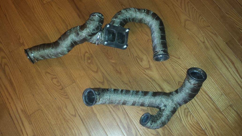
Got the merge pipe and crossover pipe leak-free. There were much fewer pinholes in these than the manifolds which I hope is an indicator that my welding is improving. Got both the pipes painted, cured, and wrapped

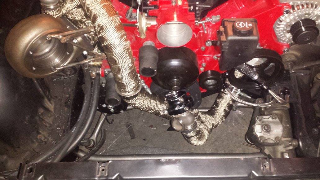
Mockup assembly of the now completed pre-turbo hot side. Thankfully this concludes the schedule 40 portion of this build. The rest of the pipe from here out will just be plain old aluminized exhaust pipe.

Another shot of the mockup assembly showing more of the crossover pipe. Everything about this build is such a tight fit--notice how close the crossover comes to both radiator hoses and how close the wastegate comes to the water pump pulley. Hopefully between the fact that the pipes are wrapped and the fact that I plan to make an extra heat shield to go around the radiator hoses, this won't cause any issues. The radiator hose itself is stainless steel (for this reason), but the ends still have to be rubber to give a place to connect to the engine. With the pre-turbo hot side complete, I'll move on to making the downpipe now.

Amazing how much faster welding goes when you don't have to grind paint off of every part inside and out beforehand. The downpipe is already mostly finished minus the o2 sensor bung, flange and bracket!

Like everything else--tight fit. Here's how much room I'll have between the inner fender and downpipe. I can either clearance the pipe with a press and/or hammer, or install polyurethane motor mounts if the rubber ones end up flexing enough to make the pipe contact and rattle.

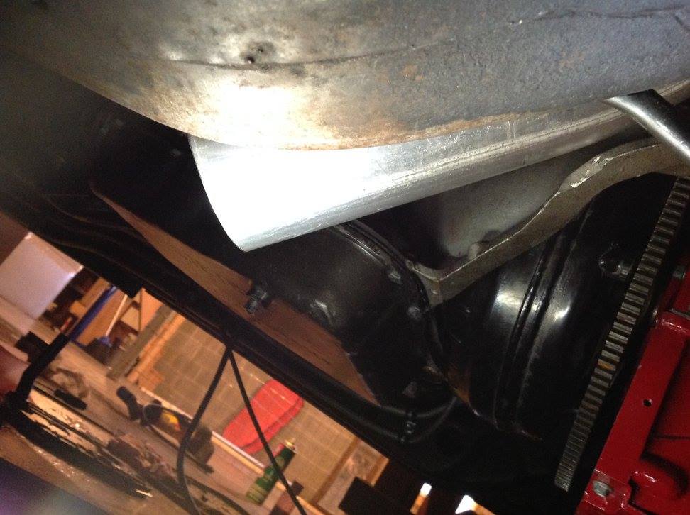
The downpipe will exit here, alongside the transmission in the factory single exhaust location. I'm hoping to squeeze the massive 4 inch pipe all the way to the back bumper, but we'll see it I can pull that off. Should sound awesome if I can!

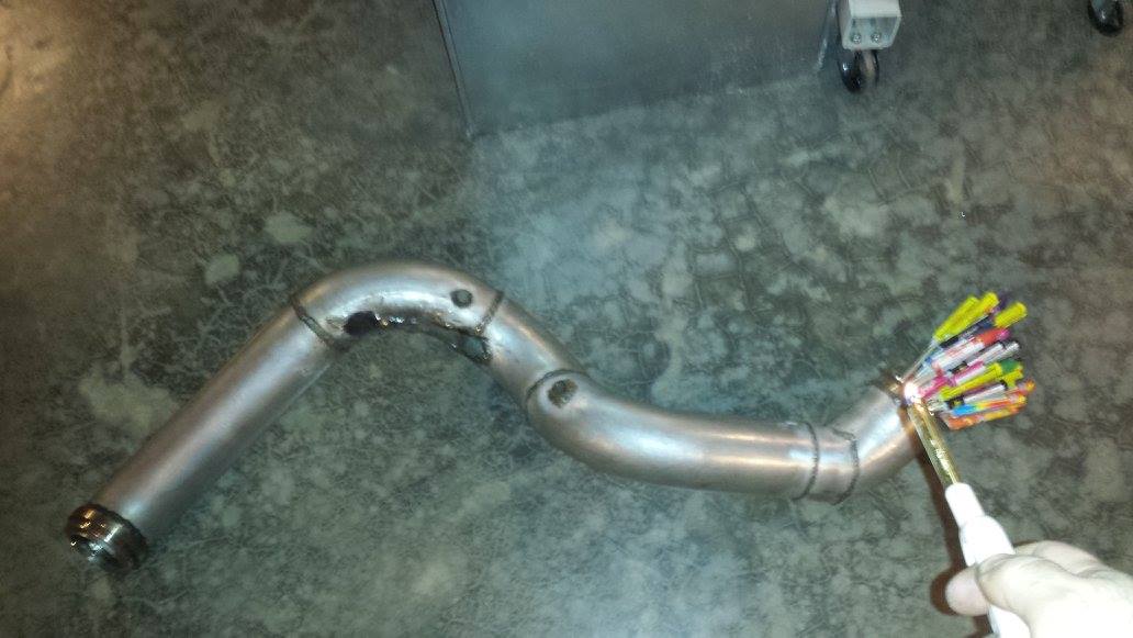
Here's where I currently am on my downpipe. Yes, those are explosives (fireworks) jammed in the end, and yes, that's me about to light them. That pretty much sums up how I feel about this thing right now. The entire thing is finished and leak free EXCEPT the passenger wastegate dump tube, which has a pinhole leak that I've chased for a cumulative total of 7 hours. I tried everything--cutting the pipe open, welding WAY up the pipe, cutting the pipe OFF, fixing, and re-attaching--ALL STILL LEAK. Finally I've resolved to cut it off completely, order new pipe, and start over on that piece of it, hence why the tube is absent from this photo. I sure hope the fabrication starts to go smoother soon or I may have to invest in more fireworks.


After approximately 3 weeks of suffering, grinding, cutting, and welding on my downpipe, I finally conceded that it was possessed by demons. I invited a couple of friends over to take care of that problem and now it is FINALLY leak free.
After the exorcism, all I had to do was replace the entire wastegate tube assembly with new pipe, grind away all traces of attempts #1-18, cut an access hole in the pipe to gain access to weld the joint inside AND out, and weld it up. Oh yeah, had to use a pint of holy water on it also.

VERY time consuming, but it's LEAK FREE now and ready to wrap. I'll post up the design and details once the wrap arrives in the mail and I get it covered.
At last, moving on to the cold side of the turbo.
