Good morning all,
In the process of replacing the brake lines and master cylinder/booster, I had to remove the bulkhead connector to get access to one of the booster bolts. While I had it out, I decided to remove the entire engine/front light harness to give it a close inspection to make sure it was still in good shape after 47 years of use. Shame on me that I did not label everything when I removed it. I figured I had the factory service manual, and I am fairly confident with my wiring abilities, what could go wrong?
Fast forward a couple of months, and I had some time last week to work on the harness. Turns out it is not as virgin as I thought it would be.
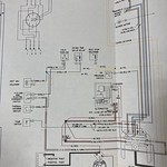
Below is a screenshot of the engine harness from the FSM. I am having issues figuring out some of these components/wires.

For example, the alternator has five wires coming out of it. The two prong plug with the two 18 gauge red and brown wires, and three wires out of the post. One red 10 gauge as shown in the diagram, and two additional 14 gauge wires that are fused at 20 amp each, and are not in the diagram. These two wires are crimped together and connected to one 14 gauge wire that runs along the same harness in the valley between the intake and valve cover and goes to a two prong connector in the back of the engine. the other prong in that connector is connected to an 18 gauge wire that goes to nowhere. There is nothing in the back of the engine for that two prong plug to connect to. Also, the fuse holders and connector both look factory, or at least vintage correct. I have owned the car 31 years, so those are not recent additions.

The fused wires coming out of alternator

Connector at the other end of the two alternator wires above
The car was originally a unitized distributor car. Only options per PHS are the AM/FM radio with 8-track, center console, and the Unitized Distributor. It is a 400/TH400. No A/C. At some point early in its life the distributor was ditched for an aftermarket HEI. The factory shows yellow and pink wire for the BAT and TACH signals, but mine has Pink and light blue, with the light blue having the resistor. The resistor was bypassed, and the power lead goes to a 20 amp fused brown wire that goes through a firewall grommet into the pass compartment. This one looks factory too, but not sure.
The car no longer has the factory Quadrajet. It has a 750DP Holley, no choke.
From the FSM, I was able to determine that I do not need the Idle Stop Solenoid (one yellow wire plug). However, I don't know what the Cold Feed Switch is for, and I don't know where the Dist Vac Solenoid is, if it has any. The TCS GRD and Downshift switch plug has the two wires (Black/org and black), but the switch in the back of the transmission where this plugs into (I think) has only one prong.

TCS downshift switch on transmission
If anyone has any insight on how to sort this out, please let me know. I have done some complex wiring on much newer cars before, but I had decent wiring diagrams to go by.
I also contacted Ames Performance to order a replacement engine harness, but those are 12-14 week lead times...
Thanks for any help.